Camber Arm Installation
*Everytime I read the forums, discussions relating to tire/camber
wear, how to get rid of camber, etc. are a non-stop issue. I've been attacked
and flamed by those who have absolutely no clue on the issue (although they think
they do), and I've been thanked and praised by those who have taken my advice
or cars I've actually adjusted myself. Each case is different according to how
and the type of driving an individual does, but in a general rule of thumb, Having
some front camber is beneficial to maximizing tire life. I would recommend about
-1.0 degrees of front camber with 0 toe in the front. This should help maximize
tire life. I won't go into detail, why? because I don't need a bombardment of
questions/flames by those who have different opinions.
**Although I purchased the camber arm to maximize camber, most will get the other model that mainly reduces
camber on lowered vehicles. Like I said, different applications, different needs,
but same installation procedure.
Tools needed: Ball
joint seperator, ratchet set, pliers to remove the cotter pin
Step1: Have at least the front jacked up and on jack stands. Make sure to choke the rear wheels.
Step2: The suspension will need to be removed. In case you need instructions, check my DIY on suspension.
*I already had a balljoint camber kit installed. It sucks. Don't get it.
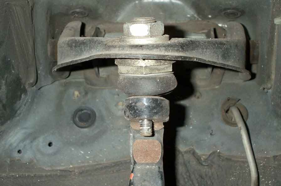
Step3: Using pliers & a flat head screwdriver (if necessary),
remove the cotter pin holding the castle nut. Once the cotter pin is removed,
unbolt the castle nut.
Step4: Use the ball joint seperator to..well, seperate the ball
joint.
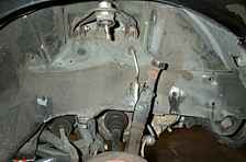
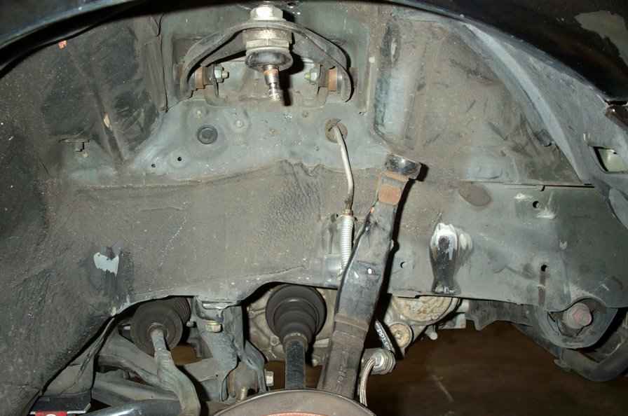
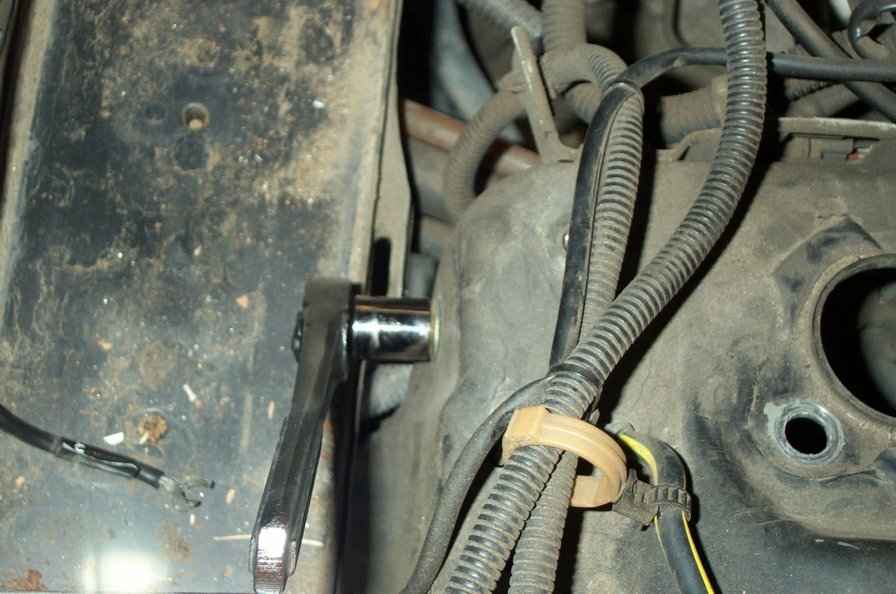
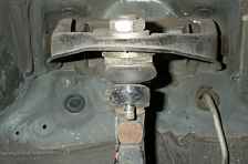
Step5: Each side of the arm is held in place by a bolt. The bolts
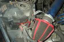
will need to be removed from the engine bay. On the passenger side, it'll be easier
by removing the battery.
Step6: Depending on what your desired camber is, start from max
out/max in/ or if you're measuring, make sure your initial settings are fairly
equal to each other. Tighten the screw caps fairly tight.
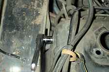
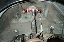
Step7: Bolt the new camber arm in place by hand tightening the
bolts on the side. Also, bolt the joint onto the spindle with the new castle nut
and cotter pin supplied with the kit. Bend the ends of the cotter pin like the
how the stock ones were as best as you can.
Step8: You can torque the castle nut first, but for the bolts
on the side of the arm, the suspension should be loaded. so either torque them
after you have the car on the ground, or use a jack to jack up the suspension
to simulate a loaded position. Torque all the bolts to spec before reinstalling
the springs/strut/or coilover.
*Torque Specs: Upper arm to chasis - 40 ft. lbs.; castle nut
- 29 to 35 ft. lbs. turn until a line matches up with the hole for the cotter
pin.
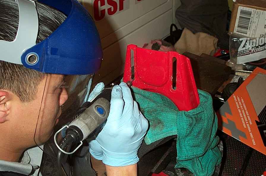
*Modifying the camber arm: the maxiumum camber the kit gave me was -2.6.
So using the metal dremel, i grided the slots a little longer to achieve the -2.8
I was looking for.

>>> Home